This shows how to add ethernet support to an Arduino using a Wiznet 5100 module, this is similar to the Ethernet shield that is commonly used but this module is a little bit more compact which may be an advantage in some projects. In this example I actually used an Arduino Nano
W5100 is a set of TCP / IP protocol, MAC and PHY in one network chip, with support for direct bus interface, SPI bus.
Features:
- Supports 10/100 Base TX
- Supports half/full duplex operation
- Supports auto-negotiation and auto cross-over detection
- IEEE 802.3/802.3u Compliance
- Operates 3.3V with 5V I/O signal tolerance
- Supports network status indicator LEDs
- Includes Hardware Internet protocols: TCP, IP Ver.4, UDP, ICMP, ARP, PPPoE, IGMP
- Includes Hardware Ethernet protocols: DLC, MAC
- Supports 4 independent connections simultaneously
- Supports MCU bus Interface and SPI Interface
- Supports Direct/Indirect mode bus access
- Supports Socket API for easy application programming
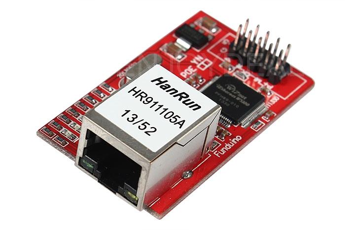
Here is the module, a lot of websites offer these
The module has some status LEDs, these are as follows
- PWR: indicates that the module is powered
- LINK: indicates the presence of a network link and flashes when data is transmitted or received
- FDX: indicates that the network connection is full duplex
- SPD: indicates the presence of a 100 Mb/s network connection (as opposed to 10 Mb/s)
- RX: flashes when data is received
- TX: flashes when data is sent
- COL: flashes when network collisions are detected
When I wired my module up and connected my network cable the first 4 LEDs were lit, the RX/TX will flash when the code example is uploaded to your board
So, the connections required are:
| PIN | Function | Arduino PIN |
| 1 | GND | GND |
| 2 | Vin 5V | +5V |
| 3 | RESET | N/C |
| 4 | SS (Slave Select) | 10 |
| 5 | SCK (SPI Interface) | 13 |
| 6 | MOSI (SPI Interface) | 11 |
| 7 | MISO (SPI Interface) | 12 |
| 8,9,10 | No Connection | N/C |
Code
This uses an example from the Ethernet library -> WebServer. You can just run that – here it is for reference.
[codesyntax lang=”cpp”]
/*
  Web Server

 A simple web server that shows the value of the analog input pins.
 using an Arduino Wiznet Ethernet shield.

 Circuit:
 * Ethernet shield attached to pins 10, 11, 12, 13
 * Analog inputs attached to pins A0 through A5 (optional)

 created 18 Dec 2009
 by David A. Mellis
 modified 9 Apr 2012
 by Tom Igoe

 */

#include <SPI.h>
#include <Ethernet.h>

// Enter a MAC address and IP address for your controller below.
// The IP address will be dependent on your local network:
byte mac[] = {
  0xDE, 0xAD, 0xBE, 0xEF, 0xFE, 0xED
};
IPAddress ip(192, 168, 0, 177);

// Initialize the Ethernet server library
// with the IP address and port you want to use
// (port 80 is default for HTTP):
EthernetServer server(80);

void setup() {
  // Open serial communications and wait for port to open:
  Serial.begin(9600);
  while (!Serial) {
    ; // wait for serial port to connect. Needed for Leonardo only
  }


  // start the Ethernet connection and the server:
  Ethernet.begin(mac, ip);
  server.begin();
  Serial.print("server is at ");
  Serial.println(Ethernet.localIP());
}


void loop() {
  // listen for incoming clients
  EthernetClient client = server.available();
  if (client) {
    Serial.println("new client");
    // an http request ends with a blank line
    boolean currentLineIsBlank = true;
    while (client.connected()) {
      if (client.available()) {
        char c = client.read();
        Serial.write(c);
        // if you've gotten to the end of the line (received a newline
        // character) and the line is blank, the http request has ended,
        // so you can send a reply
        if (c == '\n' && currentLineIsBlank) {
          // send a standard http response header
          client.println("HTTP/1.1 200 OK");
          client.println("Content-Type: text/html");
          client.println("Connection: close");  // the connection will be closed after completion of the response
          client.println("Refresh: 5");  // refresh the page automatically every 5 sec
          client.println();
          client.println("<!DOCTYPE HTML>");
          client.println("<html>");
          // output the value of each analog input pin
          for (int analogChannel = 0; analogChannel < 6; analogChannel++) {
            int sensorReading = analogRead(analogChannel);
            client.print("analog input ");
            client.print(analogChannel);
            client.print(" is ");
            client.print(sensorReading);
            client.println("<br />");
          }
          client.println("</html>");
          break;
        }
        if (c == '\n') {
          // you're starting a new line
          currentLineIsBlank = true;
        }
        else if (c != '\r') {
          // you've gotten a character on the current line
          currentLineIsBlank = false;
        }
      }
    }
    // give the web browser time to receive the data
    delay(1);
    // close the connection:
    client.stop();
    Serial.println("client disconnected");
  }
}
[/codesyntax]
Testing
Using your favourite web browser navigate to the address you setup in the code, in this case http://192.168.0.177.
I saw the following on the webpage
analog input 0 is 307
analog input 1 is 287
analog input 2 is 340
analog input 3 is 301
analog input 4 is 280
analog input 5 is 279
Links
