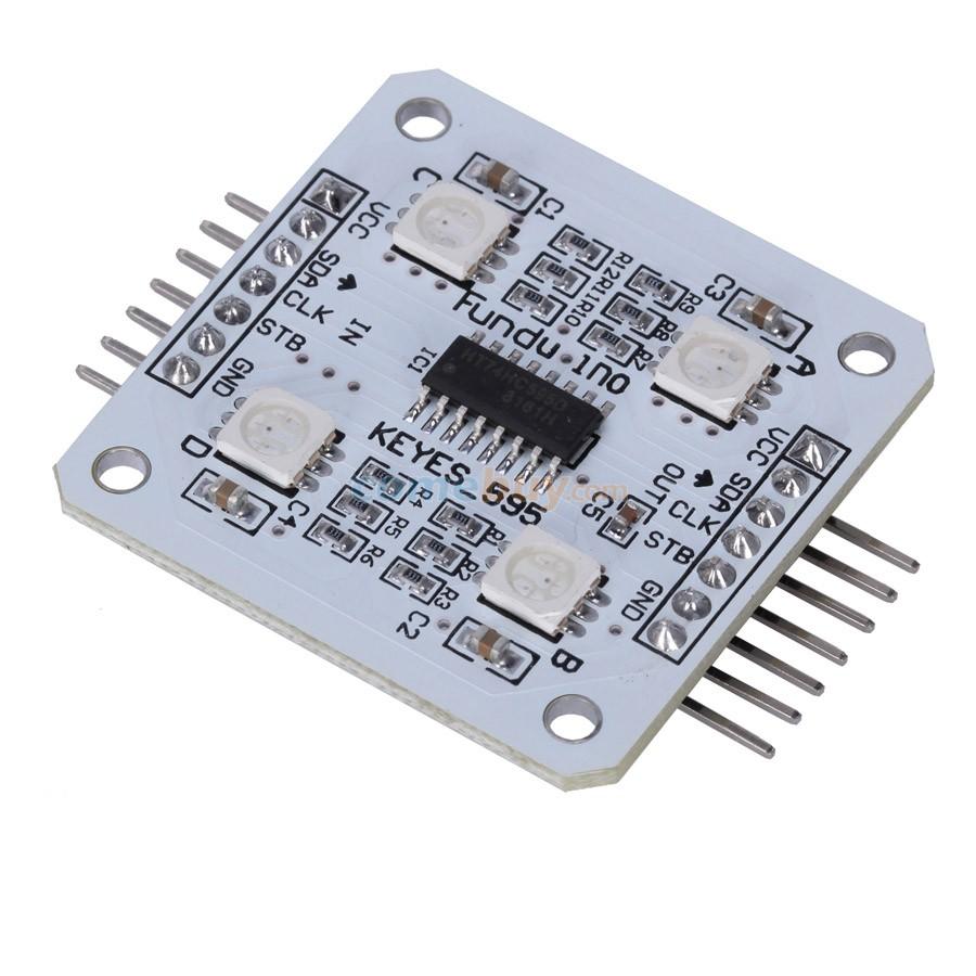
This was a module that I bought called the SPI RGB 5V 4xSMD 5050 LED Light Module for Arduino. Sadly I could not find a great deal of information for it but eventually got it to work. Looking at the module closely you can see that its a 74hc595 based IC that controls 4 SMD LEDs through an SPI interface
You connect the module to the Arduino as per the table below, I used Vcc and Gnd from the Arduino as well, these are marked on the module connector
| Arduino Pin | Module Pin |
| D11 | SDA |
| D13 | CLK |
| D8 | STB |
Code
This example requires you to download and install the ShiftPWM library from – https://github.com/elcojacobs/ShiftPWM.
This example is based on the basic RGB Example. It will produce a random flashing effect on all 4 LEDs
[codesyntax lang=”cpp”]
// ShiftPWM uses timer1 by default. To use a different timer, before '#include <ShiftPWM.h>', add
// #define SHIFTPWM_USE_TIMER2  // for Arduino Uno and earlier (Atmega328)
// #define SHIFTPWM_USE_TIMER3  // for Arduino Micro/Leonardo (Atmega32u4)

// Clock and data pins are pins from the hardware SPI, you cannot choose them yourself if you use the hardware SPI.
// Data pin is MOSI (Uno and earlier: 11, Leonardo: ICSP 4, Mega: 51, Teensy 2.0: 2, Teensy 2.0++: 22)
// Clock pin is SCK (Uno and earlier: 13, Leonardo: ICSP 3, Mega: 52, Teensy 2.0: 1, Teensy 2.0++: 21)

// You can choose the latch pin yourself.
const int ShiftPWM_latchPin=8;

// ** uncomment this part to NOT use the SPI port and change the pin numbers. This is 2.5x slower **
// #define SHIFTPWM_NOSPI
// const int ShiftPWM_dataPin = 11;
// const int ShiftPWM_clockPin = 13;


// If your LED's turn on if the pin is low, set this to true, otherwise set it to false.
const bool ShiftPWM_invertOutputs = false;

// You can enable the option below to shift the PWM phase of each shift register by 8 compared to the previous.
// This will slightly increase the interrupt load, but will prevent all PWM signals from becoming high at the same time.
// This will be a bit easier on your power supply, because the current peaks are distributed.
const bool ShiftPWM_balanceLoad = false;

#include <ShiftPWM.h>   // include ShiftPWM.h after setting the pins!

// Here you set the number of brightness levels, the update frequency and the number of shift registers.
// These values affect the load of ShiftPWM.
// Choose them wisely and use the PrintInterruptLoad() function to verify your load.
// There is a calculator on my website to estimate the load.

unsigned char maxBrightness = 255;
unsigned char pwmFrequency = 75;
int numRegisters = 1;
int numRGBleds = numRegisters*8/3;

void setup(){
  Serial.begin(9600);

  // Sets the number of 8-bit registers that are used.
  ShiftPWM.SetAmountOfRegisters(numRegisters);

  // SetPinGrouping allows flexibility in LED setup.
  // If your LED's are connected like this: RRRRGGGGBBBBRRRRGGGGBBBB, use SetPinGrouping(4).
  ShiftPWM.SetPinGrouping(1); //This is the default, but I added here to demonstrate how to use the funtion

  ShiftPWM.Start(pwmFrequency,maxBrightness);
}


void loop()
{
  // Turn all LED's off.
  ShiftPWM.SetAll(0);

  // Update random LED to random color. Funky!
    ShiftPWM.SetHSV(random(numRGBleds),random(360),255,255);
    delay(15);
}
[/codesyntax]
Link
SPI RGB 5V 4xSMD 5050 LED light module for Arduino


