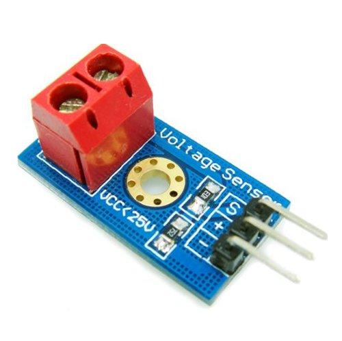
On one of my recent visits to an electronics website I saw this voltage sensor, intrigued I bought it and wondered how it worked, there didn’t seem much to it.
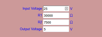
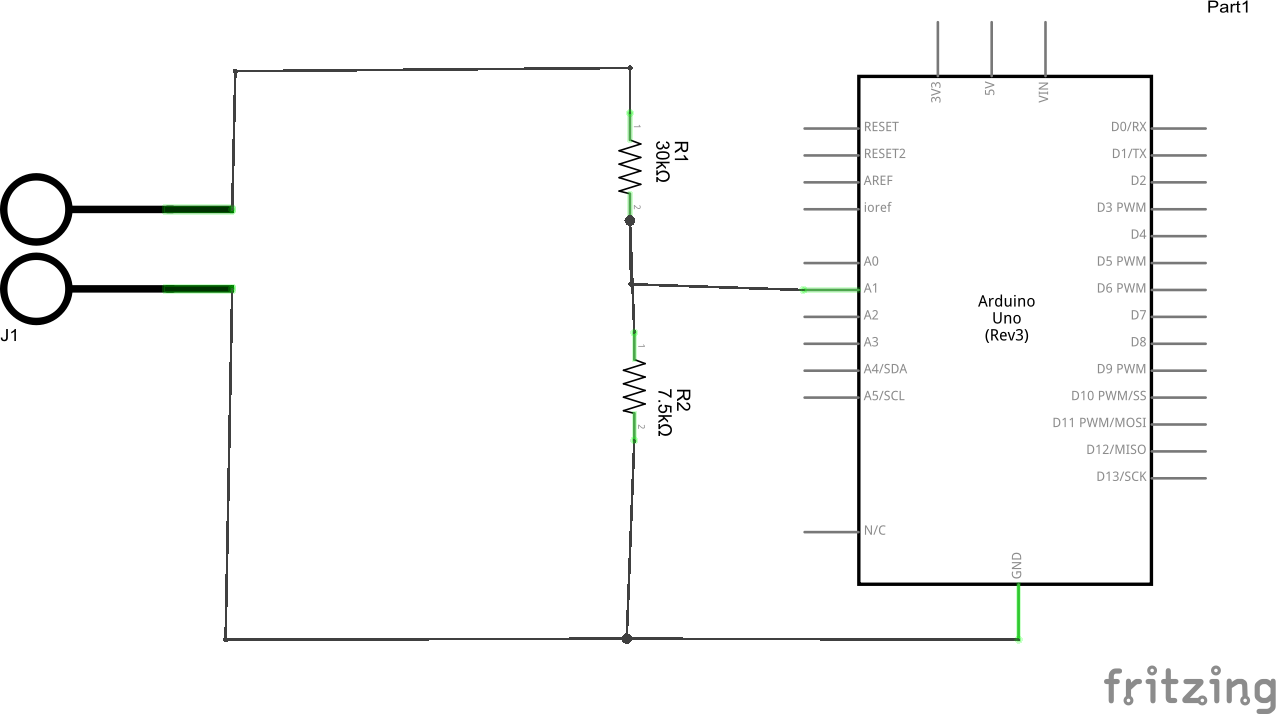
As an Arduino is limited to 5v maximum on its I/O lines I could see what was being attempted here, in fact you can quite easily build this circuit. This is simply a voltage divider with a 30k and 7k5 resistors. Basically its a 5:1 divider, so bearing in mind the 5v input limit, this circuit allows you to go up to 25v. You can punch these numbers into a voltage divider calculator, here you can see I’ve done this for you
There are a couple of connections
Vcc and GND – This is your DC power source, watch the polarity as it shares a common ground with your Arduino
S: This connects to your Arduino analog input, we use A1 you can use another if you wish
–: This connects to your Arduino ground.
+: This is not used
Schematic
Here we have drawn a representation of the sensor showing the components
Code
[codesyntax lang=”cpp”]
int analogInput = A1; // I used A1

float vout = 0.0;
float vin = 0.0;
float R1 = 30000.0; //30k
float R2 = 7500.0; //7500 ohm resistor, I tweaked this
int value = 0;

void setup()
{
   pinMode(analogInput, INPUT);
   Serial.begin(9600);
   Serial.println("BASIC DC VOLTMETER");
}

void loop()
{
   // read the value at analog input
   value = analogRead(analogInput);
   vout = (value * 5.0) / 1024.0;
   vin = vout / (R2/(R1+R2));

  Serial.print("Voltage = ");
  Serial.println(vin,2);
  delay(500);
}
[/codesyntax]
Results
Here are my results with a standard 9v battery, I measured this with my multimeter and it was actually 8.9v. you could probably tweak the values in the code above, the resistor values are what these should be in an ideal world but you’ll find that resistors have a tolerance and this may be different. You can measure the resistors using multimeter but for a low cost way of measuring say a 9v battery or a 12v dc power source its not too shabby


