This shield got my attention as it looked like a nice beginners learning type shield with which you could get up and running with an Arduino
Here is a picture of the board, a few code examples are available later on in the article.
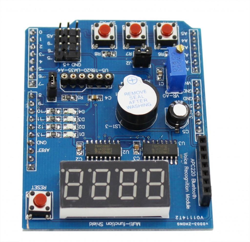
multi function shield
Features
4 digit 7-segment LED display module driven by two serial 74HC595’s
4 LED’s
10K potentiometer
3 x push buttons
Piezo buzzer
DS18B20 temperature sensor interface (not included)
Infrared receiver interface
Serial interface header for connection to serial modules
Code Examples
********************************************************************
Blinking LED
[c]
int led = 13;
void setup()
{
// initialize the digital pin as an output.
pinMode(led, OUTPUT);
}
void loop()
{
digitalWrite(led, HIGH);
delay(1000);
digitalWrite(led, LOW);
delay(1000);
}
[/c]
********************************************************************
All LEDS blinking
[c]
int led1 = 13;
int led2 = 12;
int led3 = 11;
int led4 = 10;
void setup()
{
// initialize the digital pin as an output.
pinMode(led1, OUTPUT);
pinMode(led2, OUTPUT);
pinMode(led3, OUTPUT);
pinMode(led4, OUTPUT);
}
void loop()
{
digitalWrite(led1, HIGH);
digitalWrite(led2, HIGH);
digitalWrite(led3, HIGH);
digitalWrite(led4, HIGH);
delay(1000);
digitalWrite(led1, LOW);
digitalWrite(led2, LOW);
digitalWrite(led3, LOW);
digitalWrite(led4, LOW);
delay(1000);
}
[/c]
********************************************************************
Switches example
[c]
const byte LED[] = {13,12,11,10};
#define BUTTON1 A1
#define BUTTON2 A2
void setup()
{
// initialize the digital pin as an output.
/* Set each pin to outputs */
pinMode(LED[0], OUTPUT);
pinMode(LED[1], OUTPUT);
pinMode(LED[2], OUTPUT);
pinMode(LED[3], OUTPUT);
}
void loop()
{
if(!digitalRead(BUTTON1))
{
digitalWrite(LED[0], HIGH);
digitalWrite(LED[1], HIGH);
digitalWrite(LED[2], HIGH);
digitalWrite(LED[3], HIGH);
}
if(!digitalRead(BUTTON2))
{
digitalWrite(LED[0], LOW);
digitalWrite(LED[1], LOW);
digitalWrite(LED[2], LOW);
digitalWrite(LED[3], LOW);
}
}
[/c]
********************************************************************
Potentiometer 1
[c]
#define Pot1 0
void setup()
{
Serial.begin(9600);
}
/* Main Program */
void loop()
{
Serial.print(“Potentiometer reading: “);
Serial.println(analogRead(Pot1));
/* Wait 0.5 seconds before reading again */
delay(500);
}
[/c]
********************************************************************
Pot and led
[c]
const byte LED[] = {13,12,11,10};
#define Pot1 0
void setup()
{
Serial.begin(9600);
// initialize the digital pin as an output.
/* Set each pin to outputs */
pinMode(LED[0], OUTPUT);
pinMode(LED[1], OUTPUT);
pinMode(LED[2], OUTPUT);
pinMode(LED[3], OUTPUT);
}
/* Main Program */
void loop()
{
int PotValue;
//Serial.print(“Potentiometer reading: “);
PotValue = analogRead(Pot1);
/* Wait 0.5 seconds before reading again */
if(PotValue < 400)
{
digitalWrite(LED[0], LOW);
digitalWrite(LED[1], LOW);
digitalWrite(LED[2], LOW);
digitalWrite(LED[3], LOW);
Serial.print(“Potentiometer: “);
Serial.println(PotValue);
}
else
{
digitalWrite(LED[0], HIGH);
digitalWrite(LED[1], HIGH);
digitalWrite(LED[2], HIGH);
digitalWrite(LED[3], HIGH);
Serial.print(“Potentiometer: “);
Serial.println(PotValue);
}
delay(500);
}
[/c]
********************************************************************
segment display
[c]
/* Define shift register pins used for seven segment display */
#define LATCH_DIO 4
#define CLK_DIO 7
#define DATA_DIO 8
/* Segment byte maps for numbers 0 to 9 */
const byte SEGMENT_MAP[] = {0xC0,0xF9,0xA4,0xB0,0x99,0x92,0x82,0xF8,0X80,0X90};
/* Byte maps to select digit 1 to 4 */
const byte SEGMENT_SELECT[] = {0xF1,0xF2,0xF4,0xF8};
void setup ()
{
/* Set DIO pins to outputs */
pinMode(LATCH_DIO,OUTPUT);
pinMode(CLK_DIO,OUTPUT);
pinMode(DATA_DIO,OUTPUT);
}
/* Main program */
void loop()
{
/* Update the display with the current counter value */
WriteNumberToSegment(0 , 0);
WriteNumberToSegment(1 , 1);
WriteNumberToSegment(2 , 2);
WriteNumberToSegment(3 , 3);
}
/* Write a decimal number between 0 and 9 to one of the 4 digits of the display */
void WriteNumberToSegment(byte Segment, byte Value)
{
digitalWrite(LATCH_DIO,LOW);
shiftOut(DATA_DIO, CLK_DIO, MSBFIRST, SEGMENT_MAP[Value]);
shiftOut(DATA_DIO, CLK_DIO, MSBFIRST, SEGMENT_SELECT[Segment] );
digitalWrite(LATCH_DIO,HIGH);
}
[/c]
********************************************************************
Read pot and display value on display
[c]
/* Define shift register pins used for seven segment display */
#define LATCH_DIO 4
#define CLK_DIO 7
#define DATA_DIO 8
#define Pot1 0
/* Segment byte maps for numbers 0 to 9 */
const byte SEGMENT_MAP[] = {0xC0,0xF9,0xA4,0xB0,0x99,0x92,0x82,0xF8,0X80,0X90};
/* Byte maps to select digit 1 to 4 */
const byte SEGMENT_SELECT[] = {0xF1,0xF2,0xF4,0xF8};
void setup ()
{
Serial.begin(9600);
/* Set DIO pins to outputs */
pinMode(LATCH_DIO,OUTPUT);
pinMode(CLK_DIO,OUTPUT);
pinMode(DATA_DIO,OUTPUT);
}
/* Main program */
void loop()
{
int PotValue;
PotValue = analogRead(Pot1);
Serial.print(“Potentiometer: “);
Serial.println(PotValue);
/* Update the display with the current counter value */
WriteNumberToSegment(0 , PotValue / 1000);
WriteNumberToSegment(1 , (PotValue / 100) % 10);
WriteNumberToSegment(2 , (PotValue / 10) % 10);
WriteNumberToSegment(3 , PotValue % 10);
}
/* Write a decimal number between 0 and 9 to one of the 4 digits of the display */
void WriteNumberToSegment(byte Segment, byte Value)
{
digitalWrite(LATCH_DIO,LOW);
shiftOut(DATA_DIO, CLK_DIO, MSBFIRST, SEGMENT_MAP[Value]);
shiftOut(DATA_DIO, CLK_DIO, MSBFIRST, SEGMENT_SELECT[Segment] );
digitalWrite(LATCH_DIO,HIGH);
}
[/c]
********************************************************************
Resources
Multifunctional Expansion Board Shield Kit
