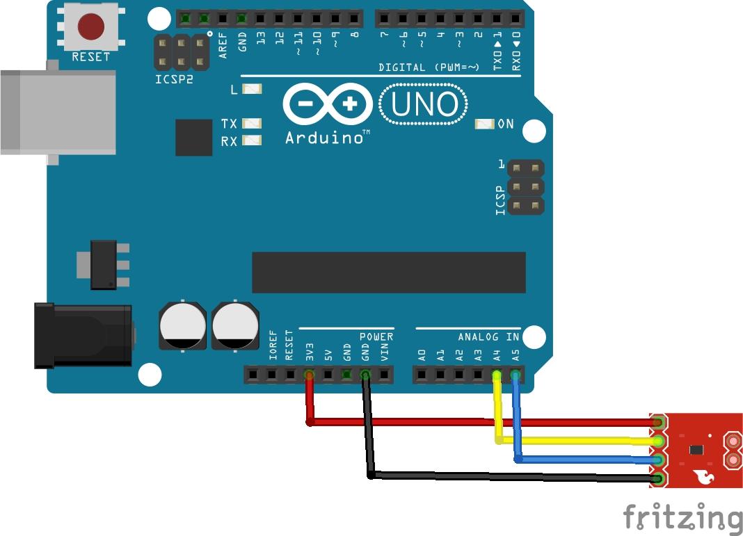
In this article we look at the TMP102 digital sensor and we will connect it up to an Arduino – lets start with some technical info about this sensor
The TMP102 device is a digital temperature sensor ideal for NTC/PTC thermistor replacement where high accuracy is required. The device offers an accuracy of ±0.5°C without requiring calibration or external component signal conditioning. Device temperature sensors are highly linear and do not require complex calculations or lookup tables to derive the temperature. The on-chip 12-bit ADC offers resolutions down to 0.0625°C.
The TMP102 device features SMBus™, two-wire and I2C interface compatibility, and allows up to four devices on one bus. The device also features an SMBus alert function. The device is specified to operate over supply voltages from 1.4 to 3.6 V with the maximum quiescent current of 10 µA over the full operating range.
The TMP102 device is ideal for extended temperature measurement in a variety of communication, computer, consumer, environmental, industrial, and instrumentation applications. The device is specified for operation over a temperature range of –40°C to 125°C.
Layout
Parts List
Code
This is from the Arduino site with a few tweaks
[codesyntax lang=”cpp”]
#include "Wire.h"
#define TMP102_I2C_ADDRESS 72 /* This is the I2C address for our chip. This value is correct if you tie the ADD0 pin to ground. See the datasheet for some other values. */


void setup()
{
  Wire.begin(); // start the I2C library
  Serial.begin(115200); //Start serial communication at 115200 baud
}


void loop()
{
  getTemp102();
  delay(5000); //wait 5 seconds before printing our next set of readings.
}

void getTemp102()
{
  byte firstbyte, secondbyte; //these are the bytes we read from the TMP102 temperature registers
  int val; /* an int is capable of storing two bytes, this is where we "chuck" the two bytes together. */
  float convertedtemp; /* We then need to multiply our two bytes by a scaling factor, mentioned in the datasheet. */
  float correctedtemp;

  /* Reset the register pointer (by default it is ready to read temperatures)
You can alter it to a writeable register and alter some of the configuration -
the sensor is capable of alerting you if the temperature is above or below a specified threshold. */

  Wire.beginTransmission(TMP102_I2C_ADDRESS); //Say hi to the sensor.
  Wire.write(0x00);
  Wire.endTransmission();
  Wire.requestFrom(TMP102_I2C_ADDRESS, 2);
  Wire.endTransmission();


  firstbyte      = (Wire.read());
  /*read the TMP102 datasheet - here we read one byte from
   each of the temperature registers on the TMP102*/
  secondbyte     = (Wire.read());
  /*The first byte contains the most significant bits, and
   the second the less significant */
    val = firstbyte;
    if ((firstbyte & 0x80) > 0)
    {
      val |= 0x0F00;
    }
    val <<= 4;
 /* MSB */
    val |= (secondbyte >> 4);
/* LSB is ORed into the second 4 bits of our byte.
Bitwise maths is a bit funky, but there's a good tutorial on the playground*/
    convertedtemp = val*0.0625;
    correctedtemp = convertedtemp - 5;
    /* See the above note on overreading */


  Serial.print("firstbyte is ");
  Serial.print("\t");
  Serial.println(firstbyte, BIN);
  Serial.print("secondbyte is ");
  Serial.print("\t");
  Serial.println(secondbyte, BIN);
  Serial.print("Concatenated byte is ");
  Serial.print("\t");
  Serial.println(val, BIN);
  Serial.print("Converted temp is ");
  Serial.print("\t");
  Serial.println(val*0.0625);
  Serial.print("Corrected temp is ");
  Serial.print("\t");
  Serial.println(correctedtemp);
  Serial.println();
}
[/codesyntax]
Output
Open the serial monitor window and you should see something like this
firstbyte is 10110
secondbyte is 11000000
Concatenated byte is 101101100
Converted temp is 22.75
Corrected temp is 17.75
firstbyte is 11100
secondbyte is 10110000
Concatenated byte is 111001011
Converted temp is 28.69
Corrected temp is 23.69
Link
http://www.ti.com/lit/gpn/tmp102


