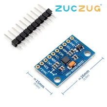
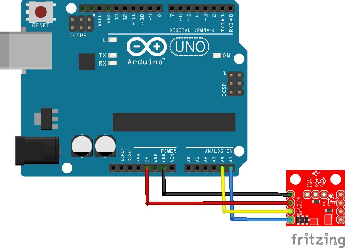
In this article we look at the MPU-9255 and an Arduino, lets look at some information about the sensor
MPU-9255 is a multi-chip module (MCM) consisting of two dies integrated into a single QFN package. One die houses the 3-Axis gyroscope and the 3-Axis accelerometer. The other die houses the AK8963 3-Axis magnetometer from Asahi Kasei Microdevices Corporation. Hence, the MPU-9255 is a 9-axis MotionTracking device that combines a 3-axis gyroscope, 3-axis accelerometer, 3-axis magnetometer and a Digital Motion Processor™ (DMP) all in a small 3x3x1mm package available as a pin-compatible upgrade from the MPU-6515.
With its dedicated I2C sensor bus, the MPU-9255 directly provides complete 9-axis MotionFusion™ output. The MPU-9255 MotionTracking device, with its 9-axis integration, on-chip MotionFusion™, and run-time calibration firmware, enables manufacturers to eliminate the costly and complex selection, qualification, and system level integration of discrete devices, guaranteeing optimal motion performance for consumers. MPU-9255 is also designed to interface with multiple non-inertial digital sensors, such as pressure sensors, on its auxiliary I2C port.
MPU-9255 features three 16-bit analog-to-digital converters (ADCs) for digitizing the gyroscope outputs, three 16-bit ADCs for digitizing the accelerometer outputs, and three 16-bit ADCs for digitizing the
magnetometer outputs. For precision tracking of both fast and slow motions, the parts feature a user programmable gyroscope full-scale range of ±250, ±500, ±1000, and ±2000°/sec (dps), a user programmable accelerometer full-scale range of ±2g, ±4g, ±8g, and ±16g, and a magnetometer full-scale range of ±4800µT.
Other industry-leading features include programmable digital filters, a precision clock with 1% drift from -40°C to 85°C, an embedded temperature sensor, and programmable interrupts. The device features I2C and SPI serial interfaces, a VDD operating range of 2.4V to 3.6V, and a separate digital IO supply, VDDIO from 1.71V to VDD.
Communication with all registers of the device is performed using either I2C at 400kHz or SPI at 1MHz. For applications requiring faster communications, the sensor and interrupt registers may be read using SPI at 20MHz.
Parts List
Schematic/Layout
Code
You need to import the https://github.com/Bill2462/MPU9255-Arduino-Library
[codesyntax lang=”cpp”]
/*
Raw data example
This example reads raw readings from the magnetometer gyroscope and the accelerometer and then
displays them in serial monitor.
*/

#include <MPU9255.h>//include MPU9255 library

MPU9255 mpu;

void setup() {
  Serial.begin(115200);//initialize Serial port

  if(mpu.init())
  {
  Serial.println("initialization failed");
  }
  else
  {
  Serial.println("initialization succesful!");
  }

}

void loop() {
  mpu.read_acc();//get data from the accelerometer
  mpu.read_gyro();//get data from the gyroscope
  mpu.read_mag();//get data from the magnetometer

  //print all data in serial monitor
  Serial.print("AX: ");
  Serial.print(mpu.ax);
  Serial.print(" AY: ");
  Serial.print(mpu.ay);
  Serial.print(" AZ: ");
  Serial.print(mpu.az);
  Serial.print("    GX: ");
  Serial.print(mpu.gx);
  Serial.print(" GY: ");
  Serial.print(mpu.gy);
  Serial.print(" GZ: ");
  Serial.print(mpu.gz);
  Serial.print("    MX: ");
  Serial.print(mpu.mx);
  Serial.print(" MY: ");
  Serial.print(mpu.my);
  Serial.print(" MZ: ");
  Serial.println(mpu.mz);
  delay(100);
}
[/codesyntax]
Output
List
https://store.invensense.com/datasheets/invensense/PS-MPU-9255.pdf


