The Microchip MCP3008 ADC is a 10-bit Analog to Digital (A/D) converter with on-board sample and hold circuitry.
Communication with the device is accomplished using a simple serial interface compatible with the SPI protocol. The MCP3008 operates over a broad voltage range (2.7V – 5.5V), and low-current design permits operation with typical standby currents of only 5 nA and typical active currents of 320 µA.
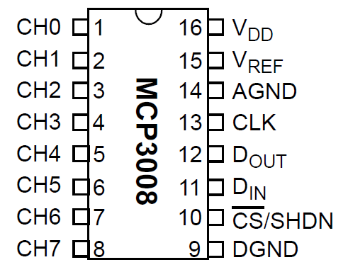
Here is the pinout of the MCP3008
Features
10bit ADC
8 channels
SPI Interface
Sampling Rate: 200kSPS
Supply Voltage 2.7V to 5.5V
Supply Current: 425µA
16 pin DIP
Conversion Time: 10µs
In the world of Arduino remember you have 6 Analog inputs but if you use I2C devices that could take care of 2 of these. So using this chip can add another 8 analog inputs, which may be useful for certain projects.
Schematics
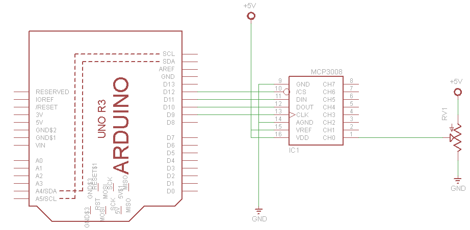
Quite basic schematic, note Pin 9 and 14 linked together and connected to ground and I connected the VREF (15) to 5v, which is pin 16. The example below shows a pot connected to CH0
Code
Based on the example from the library from https://github.com/nodesign/MCP3008. Connect Pin 1 of the MCP3008 to 0v and look at the result in the Serial monitor, do the same from 5v.
You could also connect a potentiometer or an ldr or something else that you can vary the input reading
[codesyntax lang=”cpp”]
#include <MCP3008.h>

//define pin connections
#define CS_PIN 12
#define CLOCK_PIN 9
#define MOSI_PIN 11
#define MISO_PIN 10

MCP3008 adc(CLOCK_PIN, MOSI_PIN, MISO_PIN, CS_PIN);

void setup()
{
 // open serial port
 Serial.begin(9600);
}

void loop()
{

  int val = adc.readADC(0); // read Channel 0 from MCP3008 ADC (pin 1)
  Serial.println(val);
  delay(1000);
}
[/codesyntax]
Links
You can pick these up quite easily for around $2 a piece. Also remember these are commonly used with Raspberry PIs, so if you design a little breakout board you can use it with that as well.
MCP3008-I/SL MCP3008 SOP 8-CH 10-BIT SUCCESSIVE APPROXIMATION ADC SERIAL ACCESS


