In this example we will connect an L298 to our Arduino and drive a motor. A switch will change the direction of the motor
The L298 is an integrated monolithic circuit in a 15-lead Multiwatt and PowerSO20 packages. It is a high voltage, high current dual full-bridge driver designed to accept standard TTL logic levels and drive inductive loads such as relays, solenoids, DC and stepping motors. Two enable inputs are provided to enable or disable the device independently of the input signals. The emitters of the lower transistors of each bridge are connected together and the corresponding external terminal can be used for the connection of an external sensing resistor. An additional supply input is provided so that the logic works at a lower voltage
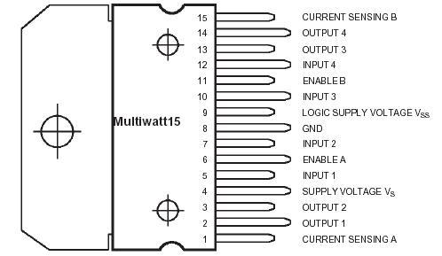
Here is the pinout of the device
Here is how you can control one of the motors, in this case Motor1. In order to activate the motor, the Enable1 line must be HIGH. You then control the motor and its direction by applying a LOW or HIGH signal to the Input1 and Input2 lines, as shown in this table.
| Input1 | Input2 | Action |
| LOW | LOW | Motor brakes and stops* |
| HIGH | LOW | Motor turns forward |
| LOW | HIGH | Motor turns backward |
| HIGH | HIGH | Motor brakes and stops* |
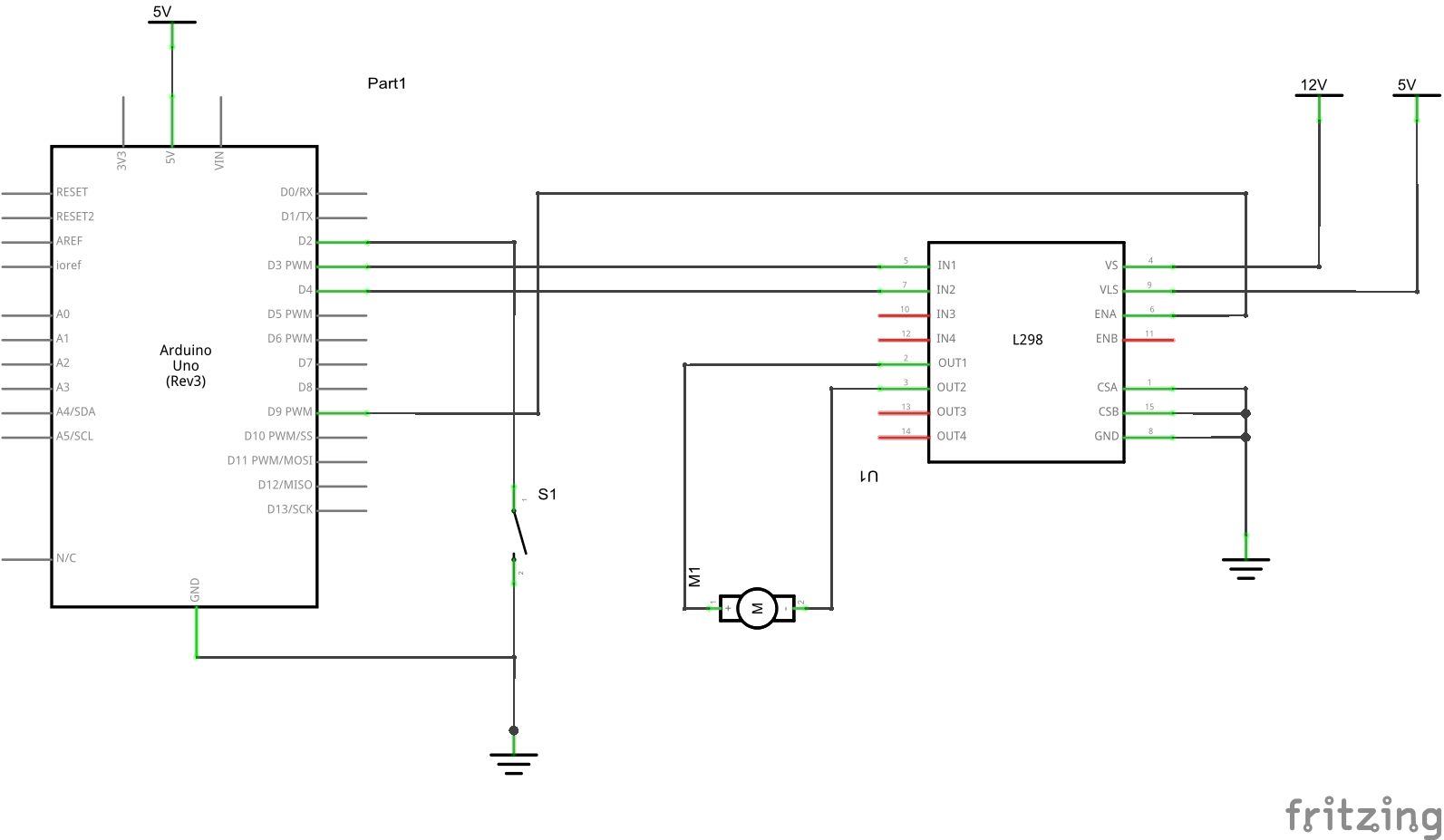
Schematic
Code
[codesyntax lang=”cpp”]
// switch pin
int switchPin = 2;
// motor pins
int motor1input1 = 3;
int motor1input2 = 4;
int enablePin = 9;

void setup()
{
    // set the switch as an input
    pinMode(switchPin, INPUT);
    // set all the other pins you're using as outputs
    pinMode(motor1input1, OUTPUT);
    pinMode(motor1input2, OUTPUT);
    pinMode(enablePin, OUTPUT);
    //turn on motor
    digitalWrite(enablePin, HIGH);
}

void loop()
{
    if (digitalRead(switchPin) == HIGH)
    {
        digitalWrite(motor1input1, LOW);
        digitalWrite(motor1input2, HIGH);
    }
    else
    {
        digitalWrite(motor1input1, HIGH);
        digitalWrite(motor1input2, LOW);
    }
}
[/codesyntax]
Link
Datasheet – http://www.st.com/web/en/resource/technical/document/datasheet/CD00000240.pdf


