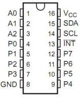
The PCF8574 is an 8 bits I/O port expander that uses the I2C protocol. Using this IC, you can use only the SDA and SCL pins of your Arduino board to control up to 8 digital I/O ports.
This 8-bit input/output (I/O) expander for the two-line bidirectional bus (I2C) is designed for 2.5-V to 6-V VCC operation.
The PCF8574 device provides general-purpose remote I/O expansion for most microcontroller families by way of the I2C interface [serial clock (SCL), serial data (SDA)].
The device features an 8-bit quasi-bidirectional I/O port (P0–P7), including latched outputs with high-current drive capability for directly driving LEDs. Each quasi-bidirectional I/O can be used as an input or output without the use of a data-direction control signal. At power on, the I/Os are high. In this mode, only a current source to VCC is active.
Features
- Low Standby-Current Consumption of 10 µA Max
- I2C to Parallel-Port Expander
- Open-Drain Interrupt Output
- Compatible With Most Microcontrollers
- Latched Outputs With High-Current Drive
Capability for Directly Driving LEDs
A0,A1,A2 are address pins
P0,P1,P2,P3,P4,P5,P6,P7 are digital I/O ports
SDA,SCL are the I2C pins
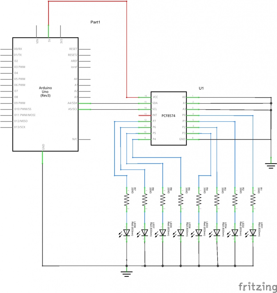
If we set pins A0 to A2 to GND, our device address in binary will be 0x20, thats exactly what I did in my example
Schematic
Note that the PCF8574 is a current sink device so you do not require the current limiting resistors but my test board had these , doesn’t do any harm just means the LEDs are a bit dimmer
Code
This example flashes the connected LEDs
[codesyntax lang=”cpp”]
#include <Wire.h>

// address of PCF8574 IC
#define PCF8574_ADDR (0x20)

void setup()
{
  Wire.begin();
}

void loop()
{


  //send the data
  Wire.beginTransmission(PCF8574_ADDR);
  Wire.write(0xAA);
  Wire.endTransmission();
  delay(1000);
  Wire.beginTransmission(PCF8574_ADDR);
  Wire.write(0x55);
  Wire.endTransmission();
  delay(1000);
}
[/codesyntax]
Link
Datasheet – http://www.ti.com/lit/gpn/pcf8574


