The ADS1115 device is a precision, low-power, 16-bit, I2C-compatible, analog-to-digital converters (ADCs) offered in an ultra-small, leadless, X2QFN-10 package, and a VSSOP-10 package. The device incorporates a low-drift voltage reference and an oscillator. The converter also incorporates a programmable gain amplifier and a digital comparator. These features, along with a wide operating supply range, make the converter well suited for power- and space-constrained, sensor measurement applications.

The ADS1115 perform conversions at data rates up to 860 samples per second (SPS). The PGA offers input ranges from ±256 mV to ±6.144 V, allowing precise large- and small-signal measurements. The converter features an input multiplexer that allows two differential or four single-ended input measurements. Use the digital comparator in the ADS1115 for under- and overvoltage detection.
The ADS1115 operates in either continuous-conversion mode or single-shot mode. The devices are automatically powered down after one conversion in single-shot mode; therefore, power consumption is significantly reduced during idle periods.
ADS1115 Features
Wide Supply Range: 2.0 V to 5.5 V
Low Current Consumption: 150 µA
(Continuous-Conversion Mode)
Programmable Data Rate: 8 SPS to 860 SPS
Single-Cycle Settling
Internal Low-Drift Voltage Reference
Internal Oscillator
I2C Interface: Four Pin-Selectable Addresses
Four Single-Ended or Two Differential Inputs
Programmable Comparator
Operating Temperature Range: –40°C to +125°C
Parts List
This module will cost less than $2
| Amount | Part Type |
|---|---|
| 1 | ADS1115 |
| 1 | UNO R3 CH340G/ATmega328P, compatible for Arduino UNO R3 |
Schematics/Layout
In the layout below we just show the Arduino and sensor , for test purposes we connect A0 to A3 to various voltages for test purposes
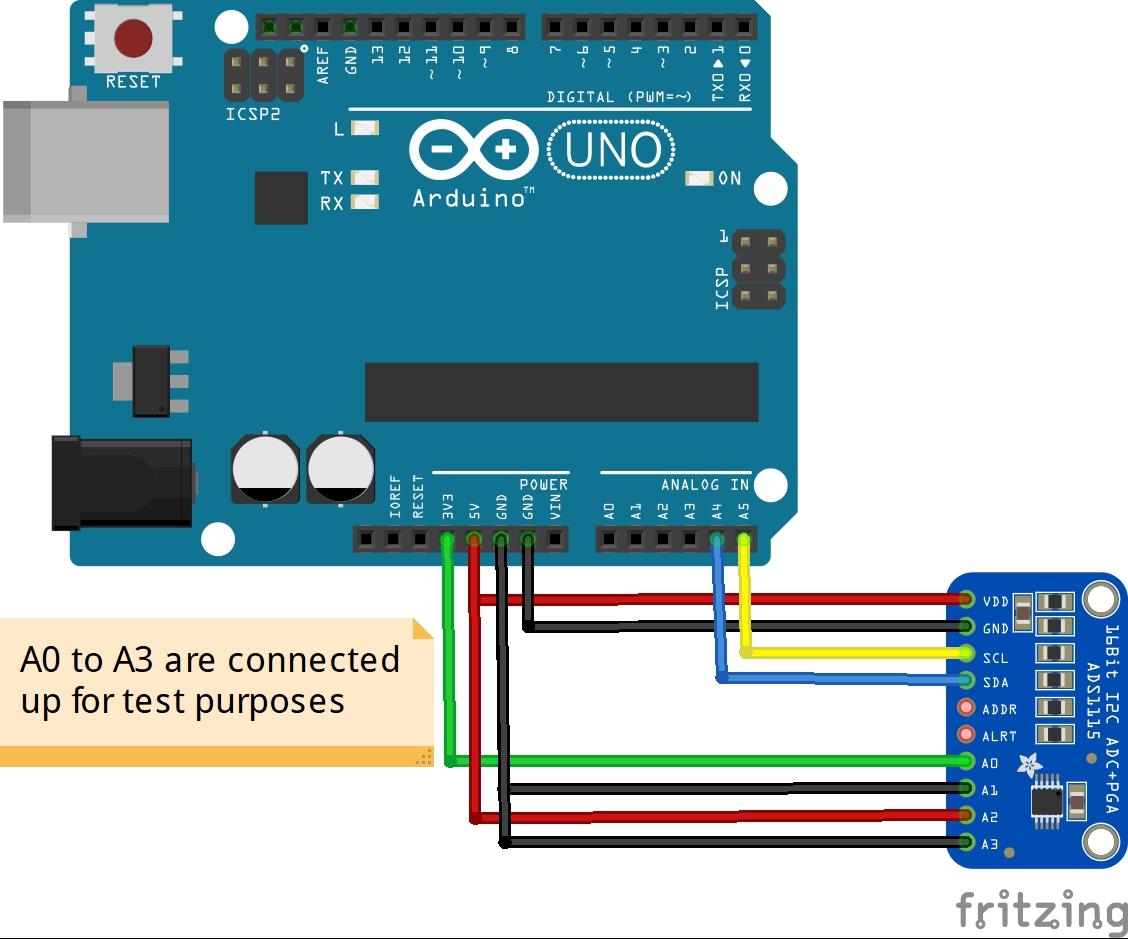
arduino and ads1115 layout
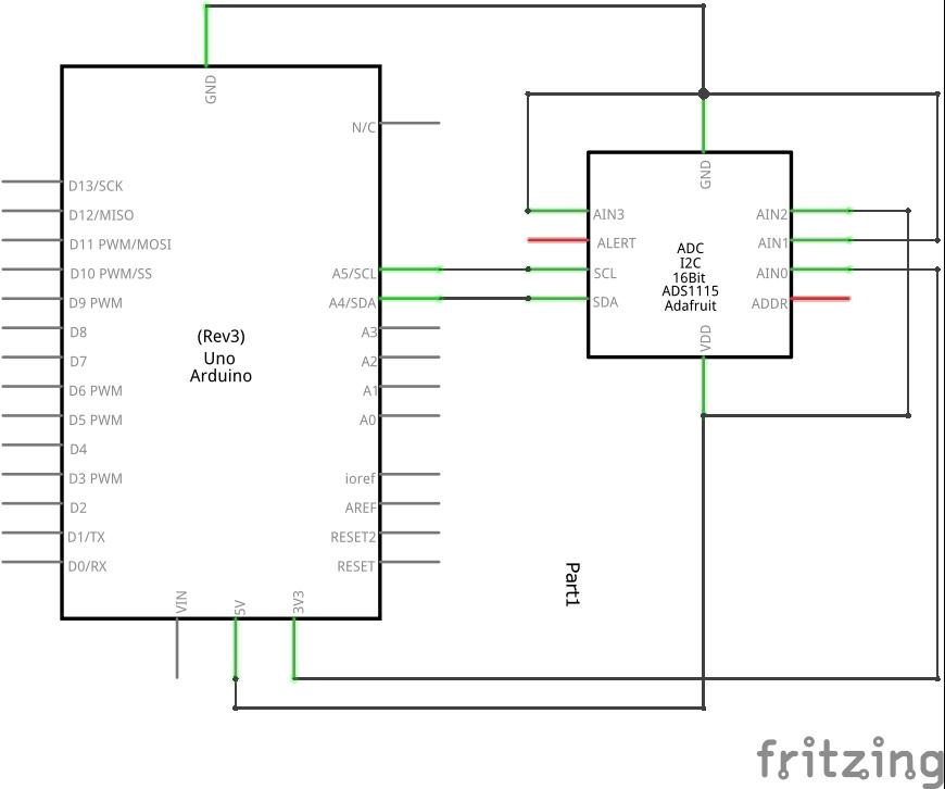
arduino and ads1115 schematic
Code
Again we use a library and again its an adafruit one – https://github.com/adafruit/Adafruit_ADS1X15
[codesyntax lang=”cpp”]
#include <Wire.h>
#include <Adafruit_ADS1015.h>

Adafruit_ADS1115 ads(0x48);

void setup(void)
{
Serial.begin(9600);
Serial.println("Hello!");

Serial.println("Getting single-ended readings from AIN0..3");
Serial.println("ADC Range: +/- 6.144V (1 bit = 3mV/ADS1015, 0.1875mV/ADS1115)");

ads.begin();
}

void loop(void)
{
int16_t adc0, adc1, adc2, adc3;

adc0 = ads.readADC_SingleEnded(0);
adc1 = ads.readADC_SingleEnded(1);
adc2 = ads.readADC_SingleEnded(2);
adc3 = ads.readADC_SingleEnded(3);
Serial.print("AIN0: ");
Serial.println(adc0);
Serial.print("AIN1: ");
Serial.println(adc1);
Serial.print("AIN2: ");
Serial.println(adc2);
Serial.print("AIN3: ");
Serial.println(adc3);
Serial.println(" ");

delay(1000);
}
[/codesyntax]
Output
Open the serial monitor and you should see something like this
AIN0: 17707
AIN1: -1
AIN2: 26295
AIN3: -1
AIN0: 17702
AIN1: -1
AIN2: 26291
AIN3: -1
AIN0: 17706
AIN1: -1
AIN2: 26289
AIN3: -1
AIN0: 17700
AIN1: -1
AIN2: 26349
AIN3: -1
Video
In this video we compile and program the Arduino and show you the output. We also show a layout and schematic in fritzing, we tied the A0 to A3 to various voltages, at the end we removed these so the input is ‘floating’
Links
http://www.ti.com/lit/ds/symlink/ads1115.pdf
I2C ADS1115 16 Bit ADC 4 channel Module with Programmable Gain Amplifier 2.0V to 5.5V RPi
