In a previous example we used the 4067 to flash some LEDs – Arduino and 4067 LED example but you can also use the CD74HC4067 multiplexer / demultiplexer to read analog values from all 16 channels. This gives you the ability to read from 16 analog inputs while only using one analog input and four digital pins.
Here is the schematic, you can use a simple voltage divider setup, potentiometers or another common input for testing with is an LDR, I had a test board with 8 sets of random resistor voltage dividers. In the schematic below I just show one of these
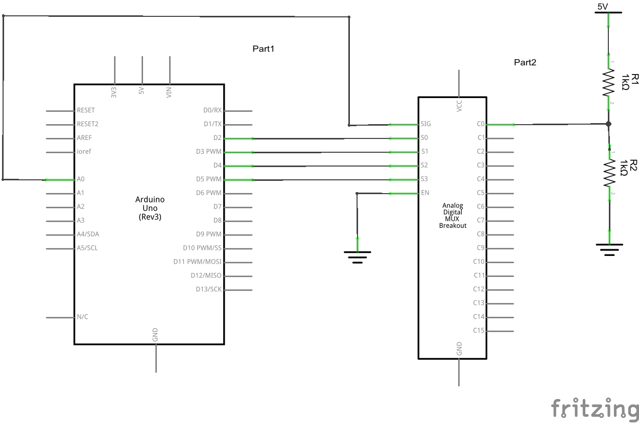
Arduino and 4067 schem
For the record in the example above if you use 1k resistors and a 5v power source then the voltage should be about 2.5v. My actual test board had random resistors of less common values I don’t use
Code
The code is fairly straightforward and loops through all of the channels and outputs the channel, value and a calculation of the voltage read via the serial monitor window
[codesyntax lang=”cpp”]
// Mux signal pin
#define muxIn 0      // Analog In Pin 0

// Mux channel select pins (change these if required)
#define muxPin0 2  // Digital Pin 2
#define muxPin1 3  // Digital Pin 3
#define muxPin2 4  // Digital Pin 4
#define muxPin3 5  // Digital Pin 5

void setup()
{
  Serial.begin(9600);
  //all pins are outputs
  pinMode(muxPin0, OUTPUT);
  pinMode(muxPin1, OUTPUT);
  pinMode(muxPin2, OUTPUT);
  pinMode(muxPin3, OUTPUT);
}

void loop()
{
  // for loop to cycle through all mux channels, 0 - 15
  Serial.println();
  Serial.println("Values from 4067");
  Serial.println("*********************************");
  for(int i = 0; i < 16; i++)
  {
    int sigValue = readMux(i);  // read from a mux channel
    Serial.print(i);
    Serial.print("\t");  // TAB
    // print the analog / digital value to the serial monitor
    Serial.print(sigValue);
    //work out the voltages based on the value read, the last value is the vRef (for me it was 4.85v
    float voltage = ((float) sigValue  + 0.5 ) / 1024.0 * 4.85;
    Serial.print("\t");
    Serial.print(voltage);
    Serial.println();      // NEW LINE
  }
  Serial.println("*********************************");
  delay(1000);
}


int readMux(int channel)
{
  digitalWrite(muxPin0, bitRead(channel, 0));
  digitalWrite(muxPin1, bitRead(channel, 1));
  digitalWrite(muxPin2, bitRead(channel, 2));
  digitalWrite(muxPin3, bitRead(channel, 3));

  // read from the selected  channel (A0)
  int muxValue = analogRead(muxIn);
  // return the  analog value
  return muxValue;
}
[/codesyntax]
Results
When you open the serial monitor window you should see something as follows, note I added the headings manually
Just for interest sake, if you look at Channel 3 you will see that I had 2.41v. This was two 10k resistors with a 4.85v voltage source and this comes out at 2.425v
| Channel | value | Voltage |
| 0 | 205 | 0.97 |
| 1 | 816 | 3.87 |
| 2 | 765 | 3.63 |
| 3 | 509 | 2.41 |
| 4 | 16 | 0.08 |
| 5 | 1005 | 4.76 |
| 6 | 69 | 0.33 |
| 7 | 118 | 0.56 |
| 8 | 183 | 0.87 |
| 9 | 129 | 0.61 |
| 10 | 141 | 0.67 |
| 11 | 108 | 0.51 |
| 12 | 67 | 0.32 |
| 13 | 103 | 0.49 |
| 14 | 65 | 0.31 |
| 15 | 62 | 0.3 |
To verify these voltages I measured the voltage on the corresponding pin on the 4067 multiplexer, I found that the values displayed were only out by 0.01v using my rough reference voltage source.
