The next module to take a look at is quite often entitled 4-CHANNEL LINE TRACKER SENSOR, thats exactly what it does the module consists of a main module and 4 little sensor/reciever modules that connect via a 3 pin cable
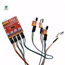
The 4-Channel Line Tracker sensor provides an easy way for line tracking. A line sensor is composed of a number cells and each cell is composed of a sender and a receiver. The particularity of this sender/receiver pair is that it sends light that shall be reflected by the line to be detected but not by the eventually opaque background surrounding this line. Any sender/receiver pair that is able to make a difference between a line and the rest of ground (of a different color) can be used in a line sensor.
VCC pin is connected to 5V , GND pin is connected to the GND, S1, S2, S3, and S4 pins are connected to the digital I/O pins 2 – 5 but you can use others
Applications:
Smart car or a robot hunt (including black and white lines), walking path along the black line, also known as tracking.
Smart car to avoid obstacle and cliff, anti-drop.
Can be applied to other automation applications of photoelectric reflex.
Specification:
Working voltage: DC 3.3V-5V
Working current: try to choose more than 1A power supply
Working temperature: -10°C to +50°C
Detection range: 1mm to 60cm adjustable, the closer the performance more stable, white reflects the farthest distance.
The output signal: TTL level (can be directly connected to I/0 microcontroller, infrared light reflected back to the sensor induction, the red indicator light, output low level; no infrared light, the indicator light does not shine, the output high.)
Module Schematic
![]()
Code
[codesyntax lang=”cpp”]
/*
Vcc - 5V
Gnd - 0V
IN1 - 4
IN2 - 5
IN3 - 6
IN4 - 7
*/

int sensorPin1 = 4;
int sensorPin2 = 5;
int sensorPin3 = 6;
int sensorPin4 = 7;

int sensorValue1 = 0;
int sensorValue2 = 0;
int sensorValue3 = 0;
int sensorValue4 = 0;

void setup()
{
 pinMode(INPUT,sensorPin1);
 pinMode(INPUT,sensorPin2);
 pinMode(INPUT,sensorPin3);
 pinMode(INPUT,sensorPin4);
 Serial.begin(9600);
}

void loop()
{
 sensorValue1 = digitalRead(sensorPin1);
 sensorValue2 = digitalRead(sensorPin2);
 sensorValue3 = digitalRead(sensorPin3);
 sensorValue4 = digitalRead(sensorPin4);

 Serial.print("Sensor 1 ");
 Serial.println(sensorValue1);
 Serial.print("Sensor 2 ");
 Serial.println(sensorValue2);
 Serial.print("Sensor 3 ");
 Serial.println(sensorValue3);
 Serial.print("Sensor 4 ");
 Serial.println(sensorValue4);
 Serial.println("***********");
 delay(1000);
}
[/codesyntax]
Output
Open the serial monitor – block and unblock the sensors
Sensor 1 0
Sensor 2 0
Sensor 3 0
Sensor 4 0
***********
Sensor 1 0
Sensor 2 0
Sensor 3 0
Sensor 4 0
***********
Sensor 1 1
Sensor 2 1
Sensor 3 1
Sensor 4 1
***********
