In this example we connect an infra red receiver to our Arduino and an RGB led. We will use various button combinations on the remote control to switch on an LED and we will use a button to switch them all off as well.
Firstly lets take a look at the kit we needed for this example to connect to our arduino and the remote control.
1. The IR breakout – low cost and easy to connect to your Arduino. This consists of the IR receiver and required additional circuitry, I used the breakout but you could build it on a breadboard if you desired
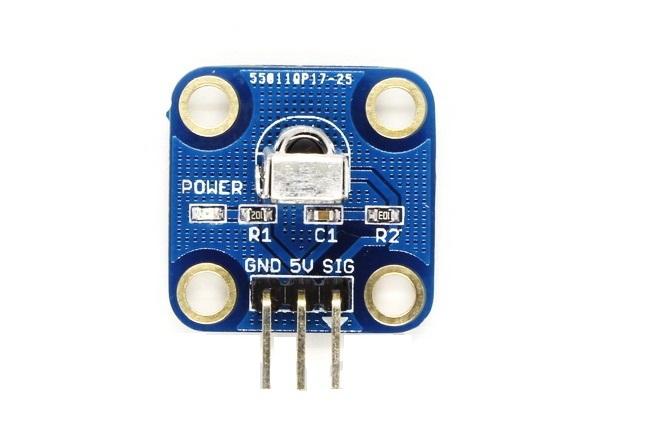
eb-infrared
2. The RGB LED – again in the form of a breakout with resistors on the breakout, this was a common anode type
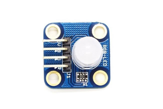
eb-rgb breakout
3. A remote control – these usually come as part of microcontroller kits but again you can find these online

Remote control
Lets take a look at the schematic of what you will build
Schematic
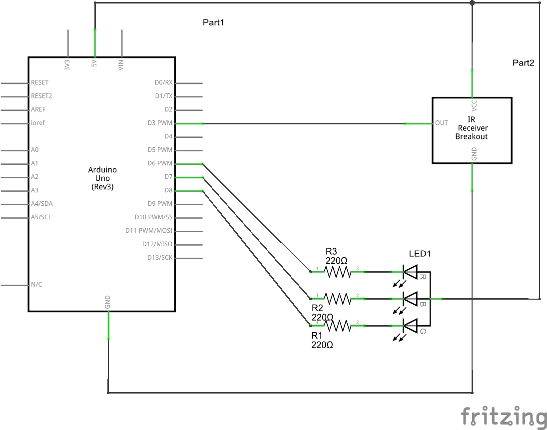
IR and RGB LED schematic
Once connected I observed that the power LED was lit on the IR breakout , so lets plan what we are doing here
Button 1 – Switch on Red lED
Button 2 – Switch on Green LED
Button 3 – Switch on Blue LED
Off Button – Switch off All LEDs
Now the first thing you need to do is upload the sketch below and discover what the codes are when you press a button on the remote control, each button is different and different types of remote controls are different as well.
There is a IR library to download and install, you can download it from here. A usual download and copy this into your Arduino -> Libraries folder. Start the IDE and enter the following
Code
[c]
#include <IRremote.h>
int receiver = 3; // pin 1 of IR receiver to Arduino digital pin 11
IRrecv irrecv(receiver); // create instance of ‘irrecv'
decode_results results;
void setup()
{
Serial.begin(9600); // for serial monitor output
irrecv.enableIRIn(); // Start the receiver
}
void loop()
{
if (irrecv.decode(&results)) // have we received an IR signal?
{
Serial.println(results.value, HEX); // display it on serial monitor in hexadecimal
irrecv.resume(); // receive the next value
}
}
[/c]
Upload the sketch and open the Serial monitor, press the desired keys and check the output. You should see something like this displayed
FF30CF
FFFFFFFF
FF18E7
FFFFFFFF
FF7A85
FFFFFFFF
FFA25D
FFFFFFFF
Wait a minute, thats two sets of hexadecimal values per button press, well the FFFFFFFF actually means that the button was held down, in our code we would want to ignore that and use the other values. This gives us the following combinations for our remote control
Button 1 – FF30CF
Button 2 – FF18E7
Button 3 – FF7A85
Off Button – FFA25D
Now for the sketch to switch on and off the RGB led. Upload this sketch
Code
[c]
#include <IRremote.h>
int RECV_PIN = 3;
int REDLED = 6;
int GREENLED = 7;
int BLUELED = 8;
IRrecv irrecv(RECV_PIN);
decode_results results;
void setup()
{
pinMode(REDLED,OUTPUT);
pinMode(GREENLED,OUTPUT);
pinMode(BLUELED,OUTPUT);
Serial.begin(9600);
irrecv.enableIRIn(); // Start the receiver
}
void loop()
{
if (irrecv.decode(&results))
{
Serial.println(results.value, HEX);
translateIR();
for (int z=0; z<2; z++) // ignore 2nd and 3rd signal repeat
{
irrecv.resume(); // receive the next value
}
}
}
void translateIR() // takes action based on IR code received
// describing Sony IR codes on LCD module
{
switch(results.value)
{
case 0xFF30CF:
digitalWrite(REDLED,LOW);
break;
case 0xFF18E7:
digitalWrite(GREENLED,LOW);
break;
case 0xFF7A85:
digitalWrite(BLUELED,LOW);
break;
case 0xFFA25D:
digitalWrite(REDLED,HIGH);
digitalWrite(GREENLED,HIGH);
digitalWrite(BLUELED,HIGH);
break;
default:
Serial.println(“OTHER”);
}
delay(500);
}
[/c]
Lets see a picture of this in action
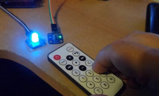
ir and rgb blue
