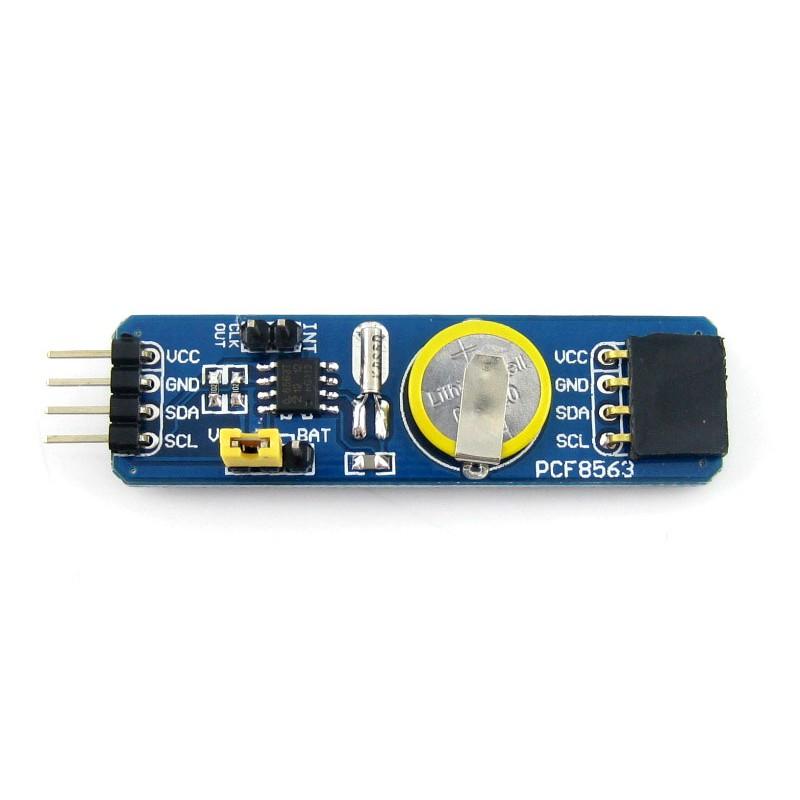
The PCF8563 is a CMOS Real-Time Clock (RTC) and calendar optimized for low power consumption. A programmable clock output, interrupt output, and voltage-low detector are also provided. All addresses and data are transferred serially via a two-line bidirectional I²C-bus. Maximum bus speed is 400 kbit/s.
This is an easy to use module for this device
Features
- Provides year, month, day, weekday, hours, minutes, and seconds based on a 32.768 kHz quartz crystal
- Century flag
- Clock operating voltage: 1.0 V to 5.5 V at room temperature
- Low backup current; typical 0.25 μA at VDD = 3.0 V and Tamb = 25 °C
- 400 kHz two-wire I²C-bus interface (at VDD = 1.8 V to 5.5 V)
- Programmable clock output for peripheral devices (32.768 kHz, 1.024 kHz, 32 Hz, and 1 Hz)
- Alarm and timer functions
- Integrated oscillator capacitor
- Internal Power-On Reset (POR)
- I²C-bus slave address: read A3h and write A2h
- Open-drain interrupt pin
This is the schematic for a typical module
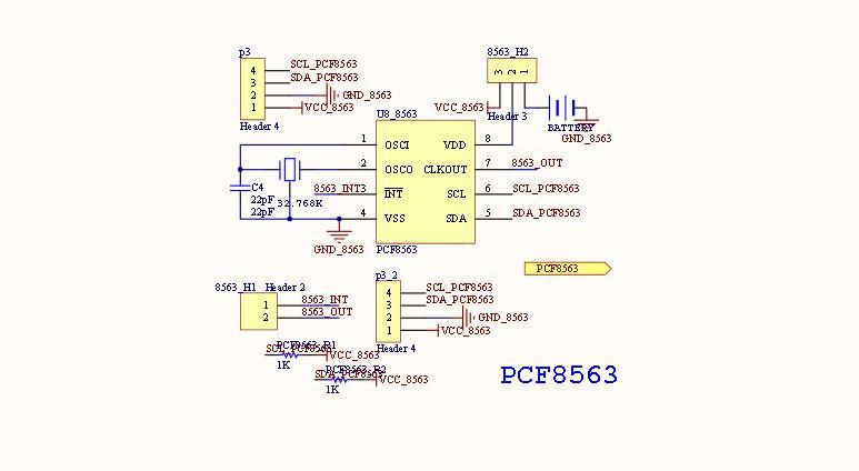
pcf8563 schematic
Here is how to connect the module to your Arduino
Connection
| Arduino Pin | Module Pin |
| 5v | Vcc |
| GND | Gnd |
| A5 | SCL |
| A4 | SDA |
Code
You do not need a library but I downloaded the library from https://bitbucket.org/orbitalair/arduino_rtc_pcf8563/downloads
This is one of the basic examples
[codesyntax lang=”cpp”]
/* Demonstration of Rtc_Pcf8563 Alarms.
 *
 * The Pcf8563 has an interrupt output, Pin3.
 * Pull Pin3 HIGH with a resistor, I used a 10kohm to 5v.
 * I used a RBBB with Arduino IDE, the pins are mapped a
 * bit differently.  Change for your hw.
 * SCK - A5, SDA - A4, INT - D3/INT1
 *
 * After loading and starting the sketch, use the serial monitor
 * to see the clock output.
 *
 * setup:  see Pcf8563 data sheet.
 *         1x 10Kohm pullup on Pin3 INT
 *         No pullups on Pin5 or Pin6 (I2C internals used)
 *         1x 0.1pf on power
 *         1x 32khz chrystal
 *
 * Joe Robertson, jmr
 * orbitalair@bellsouth.net
 */
#include <Wire.h>
#include <Rtc_Pcf8563.h>

/* get a real time clock object */
Rtc_Pcf8563 rtc;
/* a flag for the interrupt */
volatile int alarm_flag=0;

/* the interrupt service routine */
void blink()
{
  alarm_flag=1;
}

void setup()
{
  pinMode(3, INPUT);           // set pin to input
  digitalWrite(3, HIGH);       // turn on pullup resistors

  Serial.begin(9600);

  /* setup int on pin 3 of arduino */
  attachInterrupt(1, blink, FALLING);
  /* clear out all the registers */
  rtc.initClock();
  /* set a time to start with.
   * day, weekday, month, century, year */
  rtc.setDate(14, 6, 3, 0, 10);
  /* hr, min, sec */
  rtc.setTime(1, 15, 40);
  /* set an alarm for 20 secs later...
   * alarm pin goes low when match occurs
   * this triggers the interrupt routine
   * min, hr, day, weekday
   * 99 = no alarm value to be set
   */
  rtc.setAlarm(16, 99, 99, 99);
}

void loop()
{
  /* each sec update the display */
  Serial.print(rtc.formatTime());
  Serial.print("  ");
  Serial.print(rtc.formatDate());
  Serial.print("  0x");
  Serial.print(rtc.getStatus2(), HEX);
  Serial.print("\r\n");
  delay(1000);
  if (alarm_flag==1){
    clr_alarm();
  }

}

void clr_alarm()
{
  detachInterrupt(1);
  Serial.print("blink!\r\n");

  rtc.clearAlarm();
  delay(1000);
  alarm_flag=0;
  attachInterrupt(1, blink, FALLING);
}
[/codesyntax]
Links
PCF8563 RTC Board PCF8563T CMOS Real-time Clock/Calendar Development Module
