The MPU-9250 is the company’s second generation 9-axis MotionTracking device for smartphones, tablets, wearable sensors, and other consumer markets. The MPU-9250, delivered in a 3x3x1mm QFN package, is the world’s smallest 9-axis MotionTracking device and incorporates the latest InvenSense design innovations, enabling dramatically reduced chip size and power consumption, while at the same time improving performance and cost.
The MPU-9250 MotionTracking device sets a new benchmark for 9-axis performance with power consumption only 9.3µA and a size that is 44% smaller than the company’s first-generation device. Gyro noise performance is 3x better, and compass full scale range is over 4x better than competitive offerings.
The MPU-9250 is a System in Package (SiP) that combines two chips: the MPU-6500, which contains a 3-axis gyroscope, a 3-axis accelerometer, and an onboard Digital Motion Processor™ (DMP™) capable of processing complex MotionFusion algorithms; and the AK8963, the market leading 3-axis digital compass. The MPU-9250 supports InvenSense’s market proven MotionFusion. A single design can support the MPU-9250 or MPU-6500, providing customers the flexibility to support either device in different product SKUs.
Improvements include supporting the accelerometer low power mode with as little as 6.4µA of and it provides improved compass data resolution of 16-bits (0.15 µT per LSB). The full scale measurement range of ±4800µT helps alleviate compass placement challenges on complex pcb’s
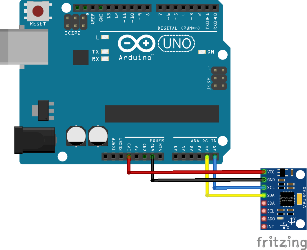
Schematic
Code
I found the code below on the internet – link below
[codesyntax lang=”cpp”]
#include <Wire.h>
#include <TimerOne.h>

#define MPU9250_ADDRESS 0x68
#define MAG_ADDRESS 0x0C

#define GYRO_FULL_SCALE_250_DPS 0x00
#define GYRO_FULL_SCALE_500_DPS 0x08
#define GYRO_FULL_SCALE_1000_DPS 0x10
#define GYRO_FULL_SCALE_2000_DPS 0x18

#define ACC_FULL_SCALE_2_G 0x00
#define ACC_FULL_SCALE_4_G 0x08
#define ACC_FULL_SCALE_8_G 0x10
#define ACC_FULL_SCALE_16_G 0x18

// This function read Nbytes bytes from I2C device at address Address.
// Put read bytes starting at register Register in the Data array.
void I2Cread(uint8_t Address, uint8_t Register, uint8_t Nbytes, uint8_t* Data)
{
// Set register address
Wire.beginTransmission(Address);
Wire.write(Register);
Wire.endTransmission();

// Read Nbytes
Wire.requestFrom(Address, Nbytes);
uint8_t index=0;
while (Wire.available())
Data[index++]=Wire.read();
}


// Write a byte (Data) in device (Address) at register (Register)
void I2CwriteByte(uint8_t Address, uint8_t Register, uint8_t Data)
{
// Set register address
Wire.beginTransmission(Address);
Wire.write(Register);
Wire.write(Data);
Wire.endTransmission();
}

// Initial time
long int ti;
volatile bool intFlag=false;

// Initializations
void setup()
{
// Arduino initializations
Wire.begin();
Serial.begin(115200);

// Set accelerometers low pass filter at 5Hz
I2CwriteByte(MPU9250_ADDRESS,29,0x06);
// Set gyroscope low pass filter at 5Hz
I2CwriteByte(MPU9250_ADDRESS,26,0x06);


// Configure gyroscope range
I2CwriteByte(MPU9250_ADDRESS,27,GYRO_FULL_SCALE_1000_DPS);
// Configure accelerometers range
I2CwriteByte(MPU9250_ADDRESS,28,ACC_FULL_SCALE_4_G);
// Set by pass mode for the magnetometers
I2CwriteByte(MPU9250_ADDRESS,0x37,0x02);

// Request continuous magnetometer measurements in 16 bits
I2CwriteByte(MAG_ADDRESS,0x0A,0x16);

pinMode(13, OUTPUT);
Timer1.initialize(10000); // initialize timer1, and set a 1/2 second period
Timer1.attachInterrupt(callback); // attaches callback() as a timer overflow interrupt


// Store initial time
ti=millis();
}

// Counter
long int cpt=0;

void callback()
{
intFlag=true;
digitalWrite(13, digitalRead(13) ^ 1);
}

// Main loop, read and display data
void loop()
{
while (!intFlag);
intFlag=false;

// Display time
Serial.print (millis()-ti,DEC);
Serial.print ("\t");


// _______________
// ::: Counter :::

// Display data counter
// Serial.print (cpt++,DEC);
// Serial.print ("\t");


// ____________________________________
// ::: accelerometer and gyroscope :::

// Read accelerometer and gyroscope
uint8_t Buf[14];
I2Cread(MPU9250_ADDRESS,0x3B,14,Buf);

// Create 16 bits values from 8 bits data

// Accelerometer
int16_t ax=-(Buf[0]<<8 | Buf[1]);
int16_t ay=-(Buf[2]<<8 | Buf[3]);
int16_t az=Buf[4]<<8 | Buf[5];

// Gyroscope
int16_t gx=-(Buf[8]<<8 | Buf[9]);
int16_t gy=-(Buf[10]<<8 | Buf[11]);
int16_t gz=Buf[12]<<8 | Buf[13];

// Display values

// Accelerometer
Serial.print (ax,DEC);
Serial.print ("\t");
Serial.print (ay,DEC);
Serial.print ("\t");
Serial.print (az,DEC);
Serial.print ("\t");

// Gyroscope
Serial.print (gx,DEC);
Serial.print ("\t");
Serial.print (gy,DEC);
Serial.print ("\t");
Serial.print (gz,DEC);
Serial.print ("\t");


// _____________________
// ::: Magnetometer :::


// Read register Status 1 and wait for the DRDY: Data Ready

uint8_t ST1;
do
{
I2Cread(MAG_ADDRESS,0x02,1,&ST1);
}
while (!(ST1&0x01));

// Read magnetometer data
uint8_t Mag[7];
I2Cread(MAG_ADDRESS,0x03,7,Mag);

// Create 16 bits values from 8 bits data

// Magnetometer
int16_t mx=-(Mag[3]<<8 | Mag[2]);
int16_t my=-(Mag[1]<<8 | Mag[0]);
int16_t mz=-(Mag[5]<<8 | Mag[4]);


// Magnetometer
Serial.print (mx+200,DEC);
Serial.print ("\t");
Serial.print (my-70,DEC);
Serial.print ("\t");
Serial.print (mz-700,DEC);
Serial.print ("\t");


// End of line
Serial.println("");
// delay(100);
}
[/codesyntax]
Links
Code above – http://www.lucidarme.me/?p=5057
Good examples – https://github.com/kriswiner/MPU9250
Datasheet – https://www.invensense.com/wp-content/uploads/2015/02/PS-MPU-9250A-01-v1.1.pdf
